
Why do computer graphics work at all?
Every image you see on a screen, whether it is pixel art, a 3D blockbuster or a VR experience is flat.
There is no depth inside your monitor. No volume, no actual light bouncing around. And yet, you instinctively recognize space, distance, shapes and materials. A character can feel close and a mountain can look far away. A light source can feel warm of cold.
This article explores how this works at a fundamental level.
We could roughly summarize computer graphics as an intersection between three different domains; human perception, mathematical projection and extremely fast numerical computation. To understand modern rendering and begin to understand graphics pipelines, shaders and lighting we should explore how we even see anything.
How human vision forms an image
The human eye
Before any signal reaches the brain, light passes through multiple physical parts that bend, focus and filter light. Computer graphics rely on mimicking the result of this process. As such we will briefly look into the (simplified) anatomy of the human eye.
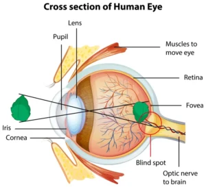
When light enters the eye it passes through the cornea. The cornea is the transparent outer layer at the front of the eye. The cornea is responsible for refracting (bending) light towards the interior of the human eye. Behind it sits the lens, which refracts the light further and together with the cornea projects a focused, inverted image onto the retina . The retina is a multi-layered curved tissue at the back of the eye that uses millions of photoreceptors to convert light into signals that our brain can use. This process of converting light or photons to signals our brain can understand via photoreceptors is called phototransduction. Another interesting thing pointed out by the above image is the fovea. The fovea is a region in the retina where the vision is sharpest.
Like any converging lens, the eye’s optical system causes light rays to cross at a focal point, which is why the image formed on the retina is inverted. This inversion is not corrected by any physical process in the brain; orientation is learned through interaction with the world, and the inverted retinal image poses no problem for perception.
Although there is a great deal of complexity in this system; far more than I could reasonably explain here or understand myself, one important observation can be made: The retina is essentially a two-dimensional surface. And yet, we experience a world with depth, distance and volume.
So where is that depth coming from?
Depth perception
If the retina only receives a two-dimensional (2D) image, then depth cannot be directly perceived or sensed. Instead, depth must be inferred. Multiple different cues allow the human brain to form a coherent three-dimensional (3D) interpretation of the world.
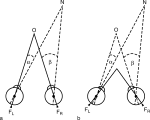
One of the strongest of these cues is binocular disparity. Because our eyes are positioned a short distance apart, each eye receives a slightly different image of the world. Objects that are nearby appear at noticeably different positions between the two retinal images, while distant objects appear nearly identical. Distances can then be triangulated. Binocular disparity is the angular difference between two landmarks viewed binocularly.
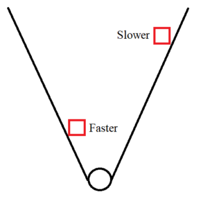
But even with one eye closed, we can still see perceive depth and the world does not suddenly appear flat. This is largely due to motion parallax. When we move our head, nearby objects will move faster across our visual field than distant ones. This provides important information about spatial layout.
In addition to these dynamic cues, a series of monocular cues can also be extracted from a single image:
- Perspective causes parallel lines to converge with distance (vanishing points).
- Objects that appear smaller are typically interpreted as being farther away.
- Occlusion tells us that one object must be obscuring the other.
- Shading and lighting provide hints about surface orientation and shape. (Also check out this thought experiment on Wikipedia.)
The key point is this: depth is not a property of the image itself. It is a hypothesis constructed by the brain based on how the image behaves, primarily when we are moving. If those images match what our brain is expecting from the physical world, then the illusion holds.
This is the fundamental truth in computer graphics. Games do not need to reproduce the world, they need to reproduce the cues our brain relies on. Everything that follows; projection, cameras, lighting, parallax and shading all exist to mimic these cues.
From 3D space to 2D images
As we move from human perception to computer graphics, a question appears: How do we turn an abstract piece of data into a two-dimensional image? Every rendering system, whether for a 2D or 3D game must answer this question.
A computer does not observe the world as a human does, there is no eye, no lens and no perception. Instead, the process of rendering begins with a piece of information or data that describes positions and shapes in some coordinate space. In a 3D game, this means we have 3-axis for width, height and depth. For 2D, the depth may be implied or ignored. In both cases we need to transform this space onto something that maps to a flat surface: the screen.
This transformation from coordinate space to screen space is called projection. If you want to dive deeper into projection I can recommend this post from geeksforgeeks.org. In the future I may make a specific blog post dedicated to the math required to do these projections, note they are not covered here. If you want to dive into this you can start by looking into projection matrices.
What do we view projections from? In computer graphics a camera is obviously not a physical object. Unfortunately there is no magic elf in the screen or little creature on a cloud with a fishing rod controlling a camera. No, in computer graphics, a camera is simply an abstraction used to define a point of view. It defines where the scene is viewed from, what orientation we have and what volume will be rendered. Everything that is outside the confines of this volume or orientation will be ignored and will not be rendered.
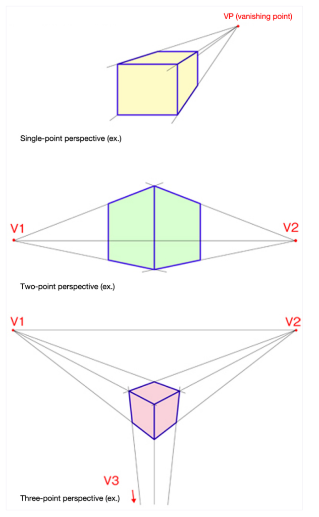
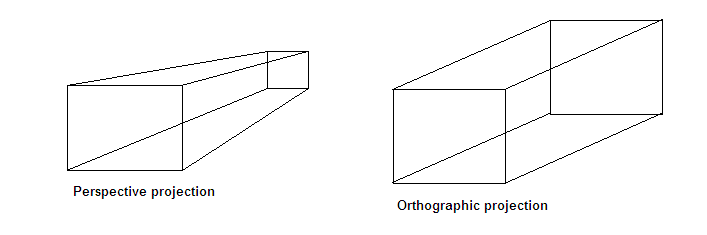
Perspective projection
The most common form of projection for games is perspective projection. It introduces distortion to match how we expect the world to behave visually.
- Objects farther from the camera appear smaller.
- Parallel lines converge.
- Depth is compressed with distance.
Do you remember the cues we learned about in the previous section? As you can see we utilise the same cues here that human perception relies on to infer depth.
Ortohographic projection
Orthographic projection can be seen as the opposite of perspective projection.
- Objects always retain their size regardless of distance.
- Parallel lines will never converge and remain parallel.
- Depth does not affect scale.
This projection is commonly used in 2D games and technical tools such as CAD programs. It often uses other cues to infer depth, such as texturing, layering and lighting.
Projection as Intentional Distortion
At this point, a useful reframing emerges. Projection is not always about accurately representing the world. It is about distorting space in such a way that a flat image can be seen as spatial.
Just as the eye’s optics project an image onto the retina, a rendering system projects abstract data onto an image plane. The similarity ends there, but the result is comparable: a two-dimensional representation that can be interpreted as three-dimensional as long as the right cues are present.
Once the projection is defined, everything else in the rendering pipeline is built on top of it. The geometry must be projected into this space, we must determine what is visible and shading and lighting must have an effect on what we drew. Eventually all of these steps lead to a single image that is visible on the screen.
A brief history of computer graphics
To understand why modern rendering works the way it does, we should briefly look at the evolution of computer graphics.
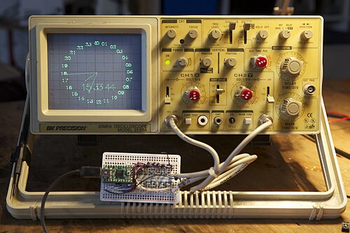
Early computer systems or displays did not work with pixels at all. Instead, they used vector displays (a specific type of CRT monitor) where lines were drawn by steering an electron beam across the screen.
The move to raster graphics, where images were represented by a grid of pixels, changed everything. It became possible to fill shapes, apply color gradients and eventually simulate lighting. The rasterization made images more predictable, and more complex scenes could be created (Fun fact, some people that play older games still use CRT monitors because the colors bleed into each other organically, which is great for particular pixel art games). When we use rasterisation we also introduce a new problem, we need to decide efficiently what pixels to draw first and in what order.

As hardware improved, graphics systems adopted a fixed-function pipeline. This pipeline defines a rigid sequence of steps that consists of transforming geometry, projecting it onto the screen, applying simple lighting models and producing a final image. Developers could configure parameters but not change the nature of the pipeline itself. This made graphics hardware fast and reliable, but also difficult to customize.
The real turning point came with the introduction of programmable shaders, introduced to the consumer market in 2001. Instead of hard-coded behaviors, developers were able to write small programs that directly ran on the graphics hardware. These programs, executed per vertex (a specific point where 2 or more lines meet) made it possible to define custom transformations, lighting models and visual effects. The GPU effectively became a massive parallel processor specialized for graphics-related math.
Modern GPU’s are the result of this evolution, they are no longer designed to draw objects, but to process a stream of data very effectively through programmable stages. You may have heard of vertex shaders, fragment shaders and render passes. These are the results of decades of advancements related to visual fidelity, performance and optimizations.
What the GPU actually does
It is tempting to think of the GPU as something that “draws” objects or understands scenes. In reality, it does neither. A GPU has no concept of characters, walls, lights, or even images. It does not know what it is rendering.
At its core, the GPU is a massively parallel numerical processor. It is designed to perform simple mathematical operations; addition, subtraction, multiplication, division and vector operations over very large sets of data. As fast as possible, and in parallel.
The reason GPUs are so effective for graphics is that rendering naturally maps to this model. Transforming thousands of vertices, shading millions of pixels, and evaluating lighting equations all involve applying the same computations repeatedly to different inputs. The GPU excels at this kind of workload and is specifically engineered for it.
This is where shaders come in. Shaders are small programs that describe how input data should be transformed. They do not represent effects or objects; they define behavior. A vertex shader describes how positions are transformed. A fragment shader describes how colors are computed. The GPU simply executes these programs over streams of data.
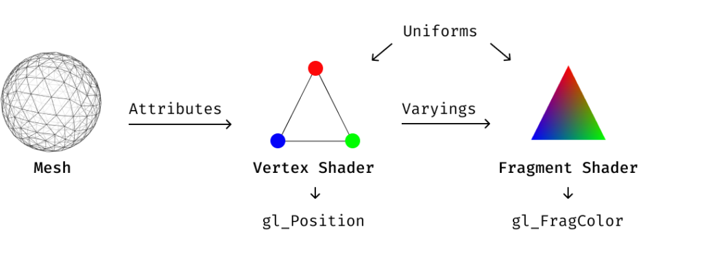
The familiar idea of a “render pipeline” does not exist as a physical machine inside the GPU. It is an abstraction imposed by graphics APIs to organize how data flows through these programs. From the GPU’s point of view, it is executing code on numbers. Note the order of operations in the above figure. We transform or process a shape or mesh using a vertex shader to modify shape, and afterwards run the fragment shader to modify color.
This distinction matters. Lighting, shading, depth, and even the illusion of space are not special features of the hardware. They are the result of consistent mathematical transformations, applied at scale.
With that mental model in place, we can now look at how those transformations are structured into a pipeline, and how data moves from geometry to pixels.
The modern render pipeline
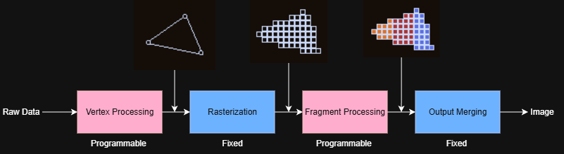
We have now established that rendering is not about drawing objects; it is about moving data through a sequence of transformations until it becomes an image. At a high level, the pipeline answers a simple question: how do abstract scene descriptions; positions, shapes, and attributes turn into colored pixels on a screen?
Data flows
The pipeline does not operate on characters, sprites, or environments. It operates on streams of data. Geometry is represented as collections of vertices, each with attributes such as position, texture coordinates, and normals. These values flow through the pipeline and are transformed step by step.
This perspective is important: nothing in the pipeline “knows” what it is rendering. Meaning is imposed entirely by how we choose to interpret the results.
Vertex shaders
The first programmable stage of the pipeline is the vertex shader. It runs once per vertex and is responsible for transforming positions from scene space into projected space. This is where projection is applied and where objects are positioned relative to the camera.
In addition to transforming positions, the vertex shader prepares data for later stages by passing attributes forward. It does not decide what things look like; it decides where things are.
Rasterization
Once vertices have been transformed, the GPU performs rasterization. Rasterization determines which pixels on the screen are covered by the projected geometry and generates fragments, which are candidates for final pixels.
During this step, vertex attributes are interpolated across surfaces. The result is a grid of fragment data ready for shading.
Fragment shaders
The fragment shader runs once per fragment and determines the final color written to the image. This is where textures are sampled, lighting is computed, and surface detail is applied.
Shading is not a special feature of the GPU. It is simply math applied per fragment. Lighting calculations, normal mapping, parallax effects, and color blending are all expressed as numerical transformations executed at scale.
At this stage, the pipeline still does not know what a surface or a light is. It only evaluates equations.
Render passes
Although the final result is a single flat image, it is often constructed in multiple passes. A render pass is simply running the pipeline again for a different purpose, often writing intermediate results to textures instead of directly to the screen.
One pass might establish base color and depth. Another might compute lighting. A final pass might combine everything into the image that is ultimately displayed. These passes exist to separate concerns and keep each step conceptually simple.
Importantly, render passes are not special hardware features. They are organizational tools built on top of the same pipeline.
Optimizations
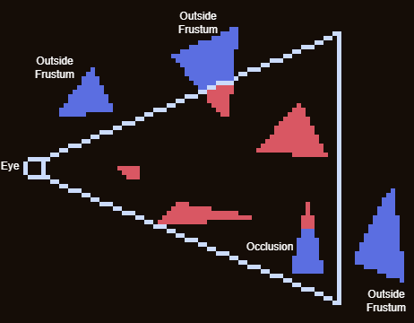
In practice, not all data that enters the render pipeline makes it to the final image. Modern rendering systems apply a range of optimizations to avoid unnecessary work, many of which happen automatically as part of the pipeline.
One common optimization is culling, which removes geometry that cannot contribute to the final image. Objects completely outside the camera’s view volume can be discarded early, as can surfaces that face away from the camera. Eliminating this data reduces the amount of work the GPU needs to perform downstream.
Closely related is clipping, which trims geometry that partially intersects the view volume. Rather than discarding an entire shape, only the visible portion is kept and processed further. This ensures correctness at screen boundaries while still limiting unnecessary computation.
Additional optimizations include depth testing, which prevents fragments that are hidden behind others from being shaded, and batching, which groups similar draw calls to reduce overhead. While these techniques differ in implementation, they all serve the same purpose: avoiding work that cannot affect the final image.
It is worth emphasizing that these optimizations do not change the fundamental nature of the render pipeline. They do not introduce new concepts or stages; they simply reduce the amount of data flowing through the existing ones. The core idea remains the same: structured data is transformed, filtered, and combined until a final image emerges.
The final image
By the time an image appears on screen, it has passed through many transformations. But understanding the structure of that process changes how you read visual problems.
When a game feels flat despite detailed art, the answer is usually a missing depth cue rather than a missing asset.
The pipeline is also a useful reminder that most of what we experience as “visual quality” is not fidelity to reality. It is the consistent presence of cues our brain is already primed to interpret. Parallax, normal mapping, ambient occlusion — none of these simulate light accurately. They simulate the signals that make us infer depth, weight and material.
Understanding the difference between simulating reality and simulating perception is probably the most useful shift in thinking that graphics programming offers. Reality is physically accurate and complex. Perception is the brain’s interpretation of signals, and that interpretation can be fooled. A flat texture with a painted shadow convinces us of depth that isn’t there. A slight camera shake implies weight and impact. Two layers moving at different speeds create the feeling of space from nothing. Graphics programming is almost never about full accuracy. It is about producing the right signals at the right time using the least computationally expensive method.
Conclusion
Thank you for reading. This article ended up being longer and more theoretical than I originally planned, but I hope it gave you a useful mental model for thinking about rendering (one that goes a little deeper than “the GPU draws things.”)
If anything here sparked curiosity, I’d encourage you to pursue this further and look into projection matrices, read about how a specific shader works, or just pay closer attention to how a game you love creates the illusion of depth!